A voltage divider is a circuit that produces an output voltage (Vout) that is a fraction of its input voltage (Vin). Voltage division is the result of distributing the input voltage among the components of the divider. When calculating with impedance the principle is valid of any combination of two resistors, capacitors, and inductors. In this tutorial we will only look at the combination of two resistors.
Voltage dividers are commonly used to create reference voltages for example by means of a potmeter or to reduce the magnitude of the voltage to values acceptable as input for the following circuit or microcontroller.
Another important usage is to translate the resistance value of resistive sensors like LDR, thermistor to a voltage suitable for further usage. In this type of usage one of the two resistors is a sensor (see tutorial on reading analog sensors).
Yet another usage is to provide a DC voltage offset when amplifying small signals using an opamp ( operational amplifier).
A voltage divider cannot be used as constant voltage power supply. Use a voltage regulator instead.
Theory
A simple example of a voltage divider is two resistors connected in series, with the input voltage applied across the resistor pair and the output voltage emerging from the connection between them.
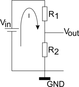
The relation between $V_{out}$ and $V_{in}$ can be derived by using Ohm’s law to calculate current $I$ assuming that the current out of the voltage divider can be neglected or $I_{out} << I$:
$$I = \frac{V_{in}}{R_1 + R_2}$$
Since $V_{out} ={I}*{R_2}$ we can calculate $V_{out}$ as function of $V_{in}$ and the resistance values.
$$V_{out} ={I}*{R_2} = \frac{R_2}{R_1 + R_2}*{V_{in}}$$
The voltage difference across $R_1$ is calculated similarly:
$$V_{R_1} ={I}*{R_1} = \frac{R_1}{R_1 + R_2}*{V_{in}}$$
If we compare $V_{R_1}$ and $V_{out}$ we see that they are proportional to the resistor value, hence the name voltage divider. In equation:
$$\frac{V_{out}}{V_{R_1}} =\frac{V_{R_2}}{V_{R_1}}= \frac{R_2}{R_1}$$
Notice that $V_{out}$ goes to 0 V when $R_2$ gets small (or $R_2 << R_1$), while $V_{out}$ goes to $V_{in}$ in the situation that $R_1$ becomes small (or $R_2 >> R_1$) . Or phrased differently: when $R_2$ decreases $V_{out}$ is pulled down towards 0 V and when $R_1$ decreases $V_{out}$ is pulled up towards $V_{in}$. When $R_1$ is equal to $R_2$, $V_{out} = \frac {V_{in}}{2}$.
Voltage divider and a load
What happens when we apply a load to the voltage divider (use it as power supply or our previous current $I_{out}$ too large to assume $I_{out} << I$)?
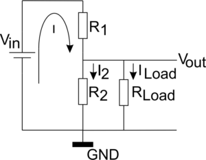
Now the current $I$ splits in a current $I_2$ through $R_2$ and $I_{Load}$ through the load with resistance $R_{Load}$. Usually $R_{Load}$ will not be in the order of kilo ohms, so a big part of the current will flow through the load and also through $R_1$. This has the danger that the power dissipation in $R_1$ exceeds its maximum rating burning out $R_1$. Next to that the output voltage $V_{out}$ will be influenced since $R_2$ of the previous calculation is now replaced by $R_2$ in parallel with $R_{Load}$ which is smaller than $R_2$ resulting in a lower output voltage.
$$R_{parallel} = \frac{1}{\frac{1}{R_2} + \frac{1}{R_{Load}}} = \frac {R_2 *R_{Load}}{R_2 + R_{Load}}$$
$$V_{out} ={I}*{R_{parallel}} = \frac{R_{parallel}}{R_1 + R_{parallel}}*{V_{in}}$$
As can be seen the output voltage $V_{out}$ is now depending on the load, which is not what you would expect from a constant voltage power supply.
Practicalities
Given the before: Do not use a voltage divider as a power supply. It is not suited for that!
A common question about voltage dividers is: “What resistor values should be used?” For this some arguments need to be considered:
- Power consumption.
Since the two resistors of a voltage divider usually connect the supply voltage to ground, they may conduct a considerable current depending on their resistance values. We don’t want that as it is merely dissipating power, but we do want a current that is large enough so the current going out through the voltage divider output is much smaller (which was an important assumption made in the calculations). Usually a current in the order of magnitude of 1 mA is sufficient for that, so for low voltage applications you may use resistors in the (tens) of kilo ohm range. - Sensitivity (in case one of the resistors is a sensor).
It can be demonstrated that the change in $V_{out}$ as function of change of the value of one of the resistors is largest (in equation $\frac{dV_{out}}{dR_i}$ is maximal, so $\frac{d^2V_{out}}{dR_i^2}=0$) when the resistor values are equal. This means that when using resistive sensors, it is best to use a value for the resistor that is the same as the resistance value of your sensor when measuring in the area of interest. - When using a micro controller like an Arduino, the properties of the ADC (Analog to Digital Converter) should be taken into account. Its resolution is expressed in bits. For an Arduino Uno the resolution is 10 bits, so since it is a 5V device it can measure voltage differences of 5V/1024 approximately 0.005V or 5mV. By using a voltage divider with two same value resistors the maximum divider output voltage range is half the supply voltage which is 2.5V for an Arduino. This can be measured in 512 5mV steps, so only one bit of resolution is lost. If the resistors are not equal, the divider output voltage range will be less, so the resolution in that range will also be less.