This tutorial has been especially created to accompany the starterskit containing an Arduino Uno microcontroller.
It will cover most of the basic skills and help to get you started with electronics.
During this tutorial you will be creating an interactive light; responding to approaching objects.
It advisable to work in small teams.
note:
Before you can start you have to make sure you also have the Arduino IDE (Integrated Development Environment) software installed on your laptop. To do so, follow the instructions on either of the following links:
https://www.arduino.cc/en/guide/windows
https://www.arduino.cc/en/guide/macOSX
Step 1 – actuator
In electronics components are distinguished into different groups.
Components which can perform an action are called actuators.
Within the interactive light an LED is used as the actuator.
The LED needs to be connected to the Arduino as shown in the schematic below.
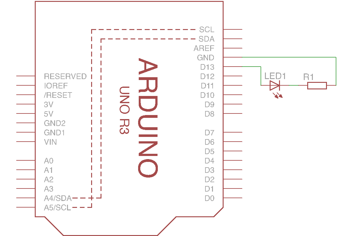
Keep in mind that LED’s have a polarity. The cathode, or the minus, is the flat side of the LED.

LED’s get damaged when the power rating (see datasheet) is exceeded. The Arduino gets damaged when its pin maximum output current (40 mA for Arduino Uno) is exceeded. To prevent this from happening we need a resistor.
The value of this resistor can be determined by Ohm’s law.
$ \displaystyle R = \frac{U}{I} $
U The voltage drop over the resistor is equal to the voltage provided by the Arduino (5 V) minus the voltage drop which is required over the LED (2.25 V for a red LED, see datasheet)
I The current through the circuit is equal to the maximum LED current (30 mA) which can be found in the datasheet
$ \displaystyle R_1 = \frac{5 – 2.25}{0.025} $
This gives a value of 91 Ohm for R1. As it is safer to use a slightly larger resistor value, in this case the 100 Ohm resistor will be used. This leads to a current of 27.5 mA which is ok for the LED as well as for the Arduino. This value can be identified by the coloured bands on the resistor.
You can easily connect the components by using the small breadboard that came with the E-Lucid starterskit. At the end of step 1 you should have something looking like this:

Step 2 – sensor
Components which can sense are called sensors. In the interactive light a proximity sensor will be used.
This sensor consists out of two parts; an infrared LED and an infrared phototransistor.
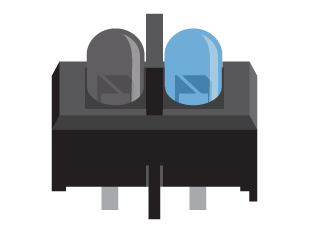
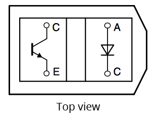
When an object is close enough the infrared light emitted by the LED is reflected into the transistor causing a high signal. Hence an object is detected.
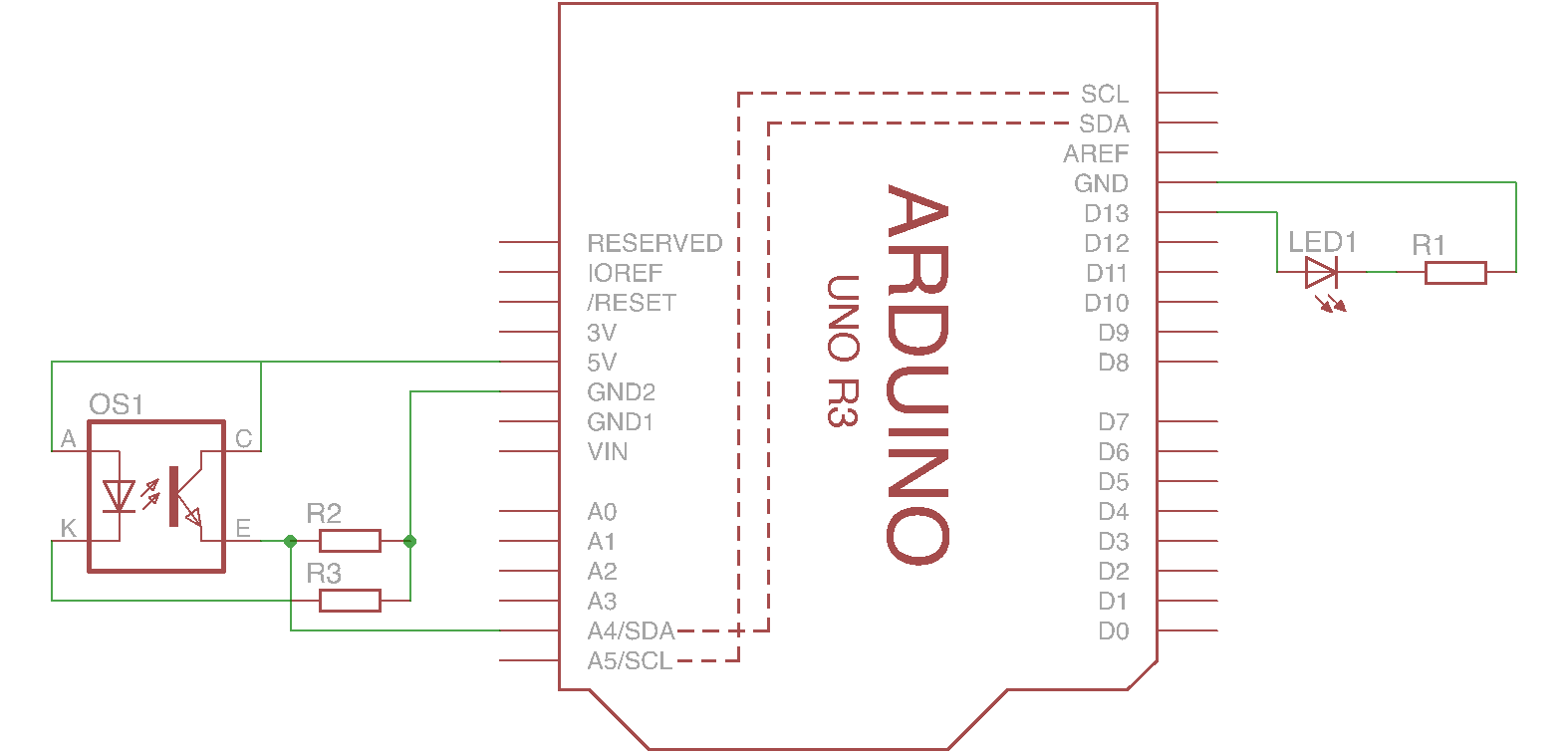
The sensor needs to be connected like shown in the schematic below. With R2 and R3 having a value of respectively 1KΩ and 150Ω.
However the sensor can’t be put directly into the breadboard. Therefore some wires need to be soldered to its legs first. Here you can read how to solder properly.

Step 3 – code
The final step in creating the interactive light is to connect the input from the sensor to the output of the actuator.
This is done in code. You can download the code below.
Within the code you can find comments explaining it.
Comments are lines preceded by “ // “. These lines are ignored when the code gets compiled and uploaded to the Arduino but are useful to make code readable.
Before uploading the code to your Arduino, set the board and port at the correct settings in the Arduino IDE (Tools/Board and Tools/Port).
Download the code below and upload it to your Arduino. Take a look at the comments in the code. Those will explain its working.
Also try to open the serial monitor or experiment with the code to change the behaviour of the light.
