In this tutorial we will explore the use of finite state machines by looking at an example. The example we will use is a railway crossing. Main focus is this tutorial is to develop the code by using finite state machines as much as possible. In that way the advantages of using them becomes clear. Code can be developed in small parts, has a clear structure and is easy to modify if needed.
What should our example do in terms of functionality or what is the main functionality of a (simplified) railway crossing?
- When no train arrives the system is idle: lights are off, gate is open, traffic can cross.
- When a train is detected by a sensor first two lights start blinking in an alternating way.
- After some time the gate closes, lights remain blinking .
- The gate stays closed, lights remain blinking till the train has passed the crossing
- The gate opens again, lights remain blinking
- The lights stop blinking and traffic can cross again.
A complication in the above process is that at any time in the process another train can be approaching for example in the situation when the gates are open again but the lights are still blinking. When a train is detected in that situation the gates should close again, lights remain blinking and the above process continuous from there so go to step 3.
So we have to elaborate a bit on additional functionality:
- When in step 2 or 3 and another train is detected: no problem, continue process as described above.
- When another train is detected in step 4 the gate should be closed longer.
- When another train is detected in step 5 the gates should close again so go to step 3 and continue from there.
Hardware used
- Arduino
- 2 LEDs with appropriate series resistors (we use 220 Ω) as indicator lights
- A servo to operate the gate
- An LDR with appropriate resistor (we use 10 kΩ) to create a voltage divider as sensor for detecting trains.
In our simplified model we have only a single sensor for incoming train detection. All other actions will be based on timing. There is no detector for trains that have passed the crossing although extending the system should be fairly easy. - An electrolytic capacitor to stabilize the supplied power especially for large current drains by the servo (e.g. 100 µF). Notice polarity while building the circuit!
Below are clickable images for the schematic and breadboard layout.
 Schematic |
 Breadboard |
Software development
We will develop the software for the railway model in several steps as indicated in article Arduino and multitasking.
In short: we will develop a state machine for each type of actuators and for the sensor that deal with all their details, next to a state machine to control the overall functionality. The overall state machine will get input from the sensor (train detected or not), it controls whether the LEDs are blinking or not, but will not implement the details of the actual blinking process. Similarly it will control and get input from the gate (whether the gate is completely opened) but it will not control the actual closing and opening processes of the gate.
All these state machines will be implemented in separate functions that will be called from within the loop() function of the Arduino code. Required initializations will be placed in the setup() function. Most variables are global and initialized when starting the program.
Convention used: All names printed in capitals are defined in the beginning of the program. Variables have in general a global scope and are declared and initialized in the beginning of the program as well.
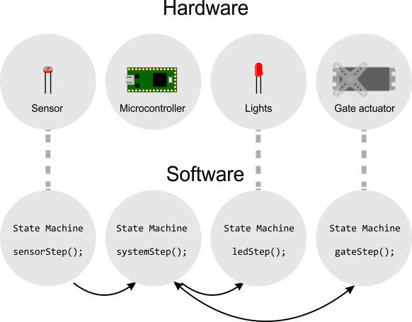
Relation of hardware and state machines in software.
Sensor
The sensor process will be handled through a function called sensorStep() which will be called from within the loop() function.
Functionality
Read the sensor value (output voltage from voltage divider). When it reaches a certain threshold value we assume a train is detected and set an appropriate indicator flag called sensorActivated from false to true. Notice that in the given circuit the sensor value increases when the LDR is covered (so it gets a higher resistance).
In code:
  if (sensorValue > sensorThreshold)   // check whether sensor is triggered or not
    sensorActivated = true;
  else
    sensorActivated = false;
Since we use an LDR that measures the light intensity, the lighting conditions of the environment may influence detection. In order to compensate for slow changes in the environment we use a so-called exponentially weighted moving average to detect the average light level in the environment and we adapt the sensor threshold value based on that. The exponentially weighted moving average algorithm does not require a lot of resources or memory but it needs to have a starting average value which will be initialized in setup().
Code
Code for definitions, declarations and initializations (beginning of program).
#define SENSOR A0      // pin for sensor detecting traffic

// settings for moving average calculation
#define AVERAGEFRACTION 0.005 // fraction needed for calculation of moving average for auto adjustment
#define THRESHOLDFACTOR 1.25  // factor for multiplying moving average to calculate threshold

int sensorValue;                   // variable for storing value read from sensor
boolean sensorActivated = false;   // variable indicating whether sensor is triggered
float sensorAvg = 0.0;             // moving average of sensorValue for automatic adjusting threshold
int sensorThreshold;               // threshold above which it is assumed that traffic is detected.
Initialization of average value done in setup()
  // initialize average value for automatic adjustment to ambient light by measuring 10 times
  for (int i = 0; i < 10; i++)
  {
    sensorAvg = sensorAvg + (float)analogRead(SENSOR);
    delay(50);
  }
  sensorAvg = sensorAvg / 10.0;
sensorStep() code.
// code for checking sensor, setting variable sensorActivated
void sensorStep()
{
  sensorValue = analogRead(SENSOR);    // read sensor

  //exponentially weighted moving average so average reacts to slow changes only
  sensorAvg = AVERAGEFRACTION * (float)sensorValue + (1 - AVERAGEFRACTION) * (float)sensorAvg;
  sensorThreshold = THRESHOLDFACTOR * sensorAvg;    // adapt threshhold to slow changes.

  if (sensorValue > sensorThreshold)   // check whether sensor is triggered or not
    sensorActivated = true;
  else
    sensorActivated = false;
}
It is a good practice to test parts of the code independently. A simple testing program for sensorStep() can be downloaded below. It prints the sensorValue and sensorActivated values to the serial port.
Download the sensorStepTest partial code below.
![]()
Actuators
We have two types of actuators the LEDs and the servo. We will develop a separate function for the process for each of them called ledStep() and servoStep() respectively.
LEDs
The led process will be handled by a function ledStep() to be called from within the loop() function.
Functionality
The LEDs can be off or they can be blinking. When they are blinking, they do that alternating meaning when one LED is on, the other one is off and after some time the second one is on and the first one is off.
For the remainder of the program (the part not handling the led process) it is only important to have control over whether the LEDs are off or whether they are blinking. That implies that changing state from off to blinking or vice versa will be by an external trigger variable. The timing required for the blinking in the blinking state can be done internally from within the ledStep() function.
LEDs state table. As mentioned there are only 2 states. We have to look what needs to happen when entering, when in, and when leaving each state.
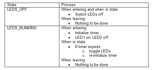
LEDs state table
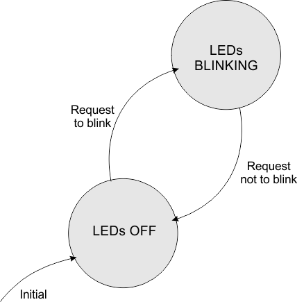
LEDs state diagram
Since we need to know whether we entered a state the first time or whether we remain in a state, we need to have a mechanism to detect that. A common approach to do that is to remember the previous state next to the current state by using an additional variable. Every time the state changes we first capture the current state value in that variable, then change the current state value to the new state value.
In (pseudo) code (do everytime when changing state):
previousState = currentState;
currentState = (value for new state);
Detection for entering a state is then done by comparing currentState and previousState. When the values are not the same we enter currentState for the first time. When all actions to be done when entering the state are performed, we set previous state equal to current state so next time we enter the function the code for remaining in the state will be executed.
In (pseudo)code:
if (currentState != previousState)
{
	// perform code to be executed when entering the state the first time
	previousState = currentState; // adjust previousState
}
else
{
	// perform code to be executed when remaining in the same state
}
The alternating on-off pattern for the LEDs is programmed using a variable indicating the status of led1 which is then toggled (in code led1Value = !led1Value) every time the timer expires. Notice the exclamation mark (logical not). Of course the value for led2 is always the opposite of the value for led1 so !led1Value. The timer is implemented using the millis() function (see Arduino and multi-tasking)
Code
Code for definitions, declarations and initializations (beginning of program)
#define LED1 11        // pin for led1
#define LED2 12        // pin for led2

#define LEDS_OFF 0      // value for state of leds: both leds off
#define LEDS_BLINK 1    // value for state of leds: leds blinking alternating
#define LED_TIMERSETTING 500     // period for led blinking time in ms

int ledState = LEDS_OFF;                 // variable indicating whether leds are blinking or not
int prevledState = LEDS_OFF;             // previous value of ledState
boolean led1Value = LOW;                 // value for state of LED1, LOW or HIGH used for blinking

unsigned long ledTimer = LED_TIMERSETTING;              // variable for timing of the blinking
Initializations done in setup()
  pinMode(LED1, OUTPUT);
  pinMode(LED2, OUTPUT);
ledStep() code
void ledStep()
{
  switch (ledState)
  {
    case LEDS_OFF:
      digitalWrite(LED1, LOW);
      digitalWrite(LED2, LOW);
      break;

    case LEDS_BLINK:
      // when entering for the first time in this state start by switching LED1 on
      // LED2 off else toggle leds after blinking period expired
      if (prevledState != ledState)
      {
        led1Value = HIGH;
        digitalWrite(LED1, led1Value);
        digitalWrite(LED2, !led1Value);
        ledTimer = millis();      // initialize timer
        prevledState = ledState;
      }
      else
      {
        if (millis() - ledTimer >= LED_TIMERSETTING)    // if blinking period expires
        {
          led1Value = !led1Value;   //toggle led1Value
          digitalWrite(LED1, led1Value);
          digitalWrite(LED2, !led1Value);
          ledTimer = millis();    // re-initialize timer
        }
      }
      break;
  }
}
Once more a separate test is good practice. Download an example test program below. This program basically switches blinking on and off based on an additional timer.
Download the ledSTepTest partial code below.
![]()
The gate
Functionality.
Of course the gate should open and close when required by the main logic part of the program. As the servo has only one single speed of opening or closing we also need some control over the (timing of the) opening and closing process. That leads to 4 different states the gate can be in: Open, closing, closed, and opening. Once again for each of these states we will have to look what needs to happen when entering, when in, and when leaving the state. This is summarized in the below table and state transition diagram.
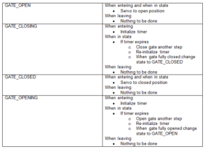
Gate state table
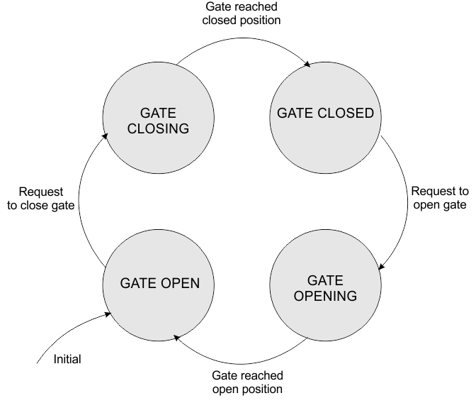
Gate state diagram
Code
Given the before, the code is quite straightforward. Defining the states and servo positions, defining and initiation of variables for controlling the state (gateState and prevgateState), timing (gateChangingTimer), and servo position (servoPos).
Initialize instance for servo (myServo) and in setup() attach it to a pin and move it to starting position.
The function gateStep() implements the finite state machine described before. An external request is needed to go to the closing or opening state, while the open and closed state are entered through a condition internal in the function. Timing for the steps when opening or closing is done through the millis() function.
Remark: The opening and closing states behavior in the code is dependent on the way the servo is positioned physically (meaning that different code is needed when SERVO_OPENPOS < SERVO_CLOSEPOS). Of course this can be included in the program at the cost of more code and an additional if statement. We decided not to do that to keep the code more readable.
Code for definitions, declarations and initializations (beginning of program).
#include <Servo.h> // add library functions needed for controlling servo

#define SERVO 10 // control signal pin for servo

#define GATE_OPEN 1 // value for state of gate: open
#define GATE_CLOSED 2 // value for state of gate: closed
#define GATE_OPENING 3 // value for state of gate: opening
#define GATE_CLOSING 4 // value for state of gate: closing
#define GATE_CHANGEPERIOD 40 // period for timing of opening/closing of gate in ms

#define SERVO_OPENPOS 90 // value for servo position when gate is open
#define SERVO_CLOSEPOS 10 // value for servo position when gate is closed
#define SERVO_STEPS 2 // number of steps made by servo per GATE_CHANGEPERIOD opening/closing

// declarations and initializations; these variables have a global scope
int gateState = GATE_OPEN; // variable indicating whether gate is open or closed
int prevgateState = GATE_OPEN; // value of gateState in previous pass of loop()

unsigned long gateChangingTimer = GATE_CHANGEPERIOD; // variable for timing opening/closing gate
int servoPos = SERVO_OPENPOS; // servo position

Servo myServo; // variable instance of servo
Initializations done in setup()
  myServo.attach(SERVO);
  myServo.write(servoPos);            // move servo to open position
gateStep() code
void gateStep()
{
  switch (gateState)
  {
    case GATE_CLOSED:
      myServo.write(SERVO_CLOSEPOS);
      break;

    case GATE_OPEN:
      myServo.write(SERVO_OPENPOS);
      break;

    case GATE_CLOSING:
      if (prevgateState != gateState) { // when entering first time
        prevgateState = gateState;
        gateChangingTimer = millis();  // initialize time for closing gate
      }
      else {
        if (millis() - gateChangingTimer >= GATE_CHANGEPERIOD) {
		  // remember SERVOPENPOS > SERVO_CLOSEPOS
          servoPos = servoPos - SERVO_STEPS;
          servoPos = constrain(servoPos, SERVO_CLOSEPOS, SERVO_OPENPOS);
          myServo.write(servoPos);
          gateChangingTimer = millis();  //re-initialize time for next step

          if (servoPos <= SERVO_CLOSEPOS) { //adapt gateState when gate closed
            gateState = GATE_CLOSED;
          }
        }
      }
      break;

    case GATE_OPENING:
      if (prevgateState != gateState) { // when entering first time
        prevgateState = gateState;
        gateChangingTimer = millis(); // initialize time for closing gate
      }
      else {
        if (millis() - gateChangingTimer >= GATE_CHANGEPERIOD) {
          // remember SERVOPENPOS > SERVO_CLOSEPOS
          servoPos = servoPos + SERVO_STEPS;
          servoPos = constrain(servoPos, SERVO_CLOSEPOS, SERVO_OPENPOS);
          myServo.write(servoPos);
          gateChangingTimer = millis();   //re-initialize time for next step

          if (servoPos >= SERVO_OPENPOS) { // adapt gateState when gate opened
            gateState = GATE_OPEN;
          }
        }
      }
      break;
  }
}
Testing program gateStepTest
For the testing program we need to consider a few things, he most important one is that closing and opening of the gate requires multiple calls to the gateStep() function as the gate is only opened and closed in small steps. The gateStep() function uses its state variable gateState for indicating whether the gate has fully opened or closed, so we will have to keep calling gateStep() until gateState changes to GATE_OPEN or GATE_CLOSED:
  prevgateState = gateState;
  gateState = GATE_CLOSING;
  while (gateState != GATE_CLOSED)    // keep calling gateStep() until gate is closed
    gateStep();
This is done in a while loop e.g. for closing the gate. The remainder of the loop of the test program should be clear from the code.
You can download the gateStepTest test program below.
![]()
System logic
Functionality.
So far we have developed a number of functions that read the input and control the output, mostly by using finite state machines implementations. The final step is to combine all these functions in order to achieve the overall functionality of the railway crossing. The functionality is already described in text in the introduction of this tutorial. Now it is time to implement it, first in an abstract form as a finite state machine. Later as code as well.
From the description we can distinguish a number of system level states:
- IDLE: lights off, gate open
- BLINKING BEFORE CLOSING: lights blinking, gate still open
- CLOSING GATE: lights remain blinking, gate slowly closing
- GATE CLOSED: lights remain blinking, gate closed.
- OPENING GATE: lights remain blinking, gate slowly opening.
- BLINKING AFTER OPENING: lights remain blinking, gate open
Once more we make a state table and state transition diagram looking at what needs to happen when entering, when in, and when leaving the state. A complication in this case is that in every state another train can be detected and we need to take appropriate action.
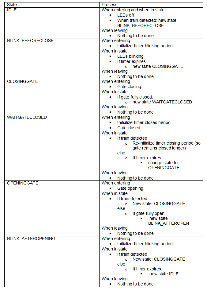
System state table
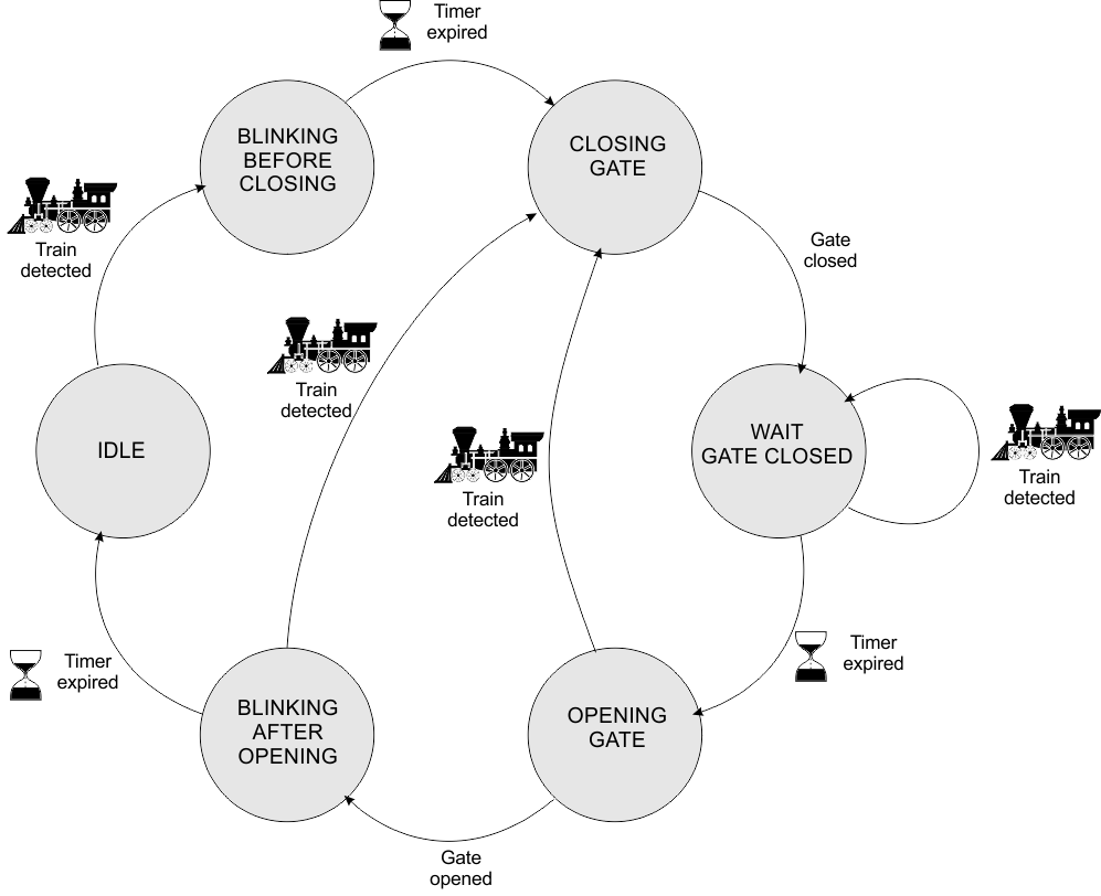
System state diagram
Data flow diagram
The core functionality described before is programmed in a separate function systemStep() which will be called everytime the code in loop() runs. The below data flow diagram illustrates the communication between all the …step() functions. The systemStep() function controls the main functionality by reading the variables sensorActivated (detect trains) and gateState (check whether the gate has fully opened or closed). systemStep() controls the LEDs through setting ledState and the gate through setting gateState at specific values.
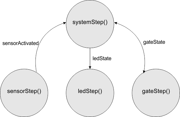
Data flow diagram
Code
The finites state machine described before is again implemented through a switch statement. Since it uses many parts of code similar to those discussed before, it should be understandable without much explanation.
Code for definitions, declarations and initializations (beginning of program).
// values for defining system states
#define SYSTEM_IDLE 0               // waiting for a train, gate open, lights off
#define SYSTEM_BLINK_BEFORECLOSE 1  // train detected, lights blinking, gate open
#define SYSTEM_CLOSINGGATE 2        // lights blinking, gate closing
#define SYSTEM_WAITGATECLOSED 3     // lights blinking, gate stays closed for certain time
#define SYSTEM_OPENINGGATE 4        // gate opening again, lights blinking
#define SYSTEM_BLINK_AFTEROPEN  5   // lights keep blinking for a certain time

int systemState = SYSTEM_IDLE;      // variable for indication of system state
int prevsystemState = SYSTEM_IDLE;  // gateState in previous pass of loop()

// variable for timing the period of blinking
unsigned long ledBlinkperiodTimer = LED_BLINKPERIOD;
// variable for timing the period the gate is closed
unsigned long gateClosedTimer = GATE_CLOSEDPERIOD;
Code for systemStep()
void systemStep() {
  switch (systemState)
  {
    case SYSTEM_IDLE:
      if (sensorActivated == true)     // if train detected: blinking lights
      {
        systemState = SYSTEM_BLINK_BEFORECLOSE;
      }
      else
      {
        prevledState = ledState;
        ledState = LEDS_OFF;
      }
      break;

    case SYSTEM_BLINK_BEFORECLOSE:
      if (systemState != prevsystemState)   // when entering first time
      {
        prevsystemState = systemState;
        ledBlinkperiodTimer = millis();     // initialize blink period timer
      }
      else {
        prevledState = ledState;
        ledState = LEDS_BLINK;
		// if blink period ends: close gate
        if (millis() - ledBlinkperiodTimer >= LED_BLINKPERIOD) {
          systemState = SYSTEM_CLOSINGGATE;
        }
      }
      break;

    case SYSTEM_CLOSINGGATE:
      if (systemState != prevsystemState) {   // when entering first time
        prevsystemState = systemState;
        gateState = GATE_CLOSING;
      }
      else {
        if (gateState == GATE_CLOSED) {
          systemState = SYSTEM_WAITGATECLOSED;
        }
      }
      break;

    case SYSTEM_WAITGATECLOSED:
      if (systemState != prevsystemState) {   // when entering first time
        prevsystemState = systemState;
        gateClosedTimer = millis();     // initialize gate closed timer
      }
      else {
        if (sensorActivated == true)   // new train:re-initialize waiting time
          gateClosedTimer = millis();
        else
        {
		// if gate closed period ends: open gate
		if (millis() - gateClosedTimer >= GATE_CLOSEDPERIOD)
          {
            systemState = SYSTEM_OPENINGGATE;
          }
        }
      }
      break;

    case SYSTEM_OPENINGGATE:
      if (systemState != prevsystemState) {   // when entering first time
        prevsystemState = systemState;
        gateState = GATE_OPENING;
      }
      else {
        if (sensorActivated == true)
		// new train:gate closing again
        {
          systemState = SYSTEM_CLOSINGGATE;
        }
        else
        {
          if (gateState == GATE_OPEN) {
            systemState = SYSTEM_BLINK_AFTEROPEN;
          }
        }
      }
      break;

    case SYSTEM_BLINK_AFTEROPEN:
      if (systemState != prevsystemState) {   // when entering first time
        prevsystemState = systemState;
        ledBlinkperiodTimer = millis();       // initialize timer
      }
      else {
        if (sensorActivated == true) {       // new train: close gate again
          systemState = SYSTEM_CLOSINGGATE;
          gateState = GATE_CLOSING;
        }
        else
        {
          // if blink period ends: leds off, return to idle
          if (millis() - ledBlinkperiodTimer >= LED_BLINKPERIOD)
            systemState = SYSTEM_IDLE;
        }
      }
      break;
  }
}
Final code loop()
Since everything is coded in separate step functions the overall loop() code is simple: call all the step functions.
void loop() {
  // this code runs continuously
  sensorStep();     // check sensor, will set variable sensorActivated

  systemStep();     // perform the functionality on system level

  ledStep();        // perform activities related to blinking of leds
  gateStep();       // perform activities related to servo closing gate

#if defined (DEBUGINFO)   // conditional compiling in for debugging
  printDebug();    // printing of debugging information through serial port.
#endif

  //for quick & dirty debugging: led on when system state is even, off otherwise.
  digitalWrite(ONBOARDLED, systemState % 2 == 0);
}
You may notice some additional code at the end of loop(). This is intended for debugging and will be described in more detail below.
Additional code for debugging
Since the complete code can best be debugged when it is running, it is important to have some debugging information. This is implemented in a function printDebug() that prints the most important variable values (sensorValue and moving average, and state values) in a single line to the serial monitor. Notice the ‘\t’ which in C-code is the TAB character.
printDebug()is switched on/off by defining a pre-processor variable DEBUGINFO. When commented out (so //#define DEBUGINFO) there is no debug info. When not commented out, debug info will be printed. We use conditional compiling. The serial library is only compiled and loaded when needed, which saves program memory.
Code
Code for definitions, declarations and initializations (beginning of program).
/* when this variable is defined debug information is printed to the serial port.
   Comment out for no debugging */
//#define DEBUGINFO
In setup()
#if defined (DEBUGINFO)  // conditional compiling for debugging
  // initiate Serial port for debugging through serial monitor.
  Serial.begin(9600);
#endif
Call in loop()
#if defined (DEBUGINFO)   // conditional compiling in for debugging
  printDebug();    // printing of debugging information through serial port.
#endif
And finally the printdebug() code which again uses conditional compiling
#if defined (DEBUGINFO)
void printDebug()
// code for printing information for debugging
{
  Serial.print("sensorValue:"); Serial.print(sensorValue); Serial.print('\t');
  Serial.print("sensorAvg:"); Serial.print(sensorAvg); Serial.print('\t');
  Serial.print("sensorActivated:"); Serial.print(sensorActivated); Serial.print('\t');
  Serial.print("systemState:"); Serial.print(systemState); Serial.print('\t');
  Serial.print("ledState:"); Serial.print(ledState); Serial.print('\t');
  Serial.print("gateState:"); Serial.print(gateState); Serial.print('\t');
  Serial.println();
}
#endif
An additional way of debugging is implemented through the built-in LED. It implements that the LED is on when systemState is even and is off otherwise. In this way it is easy to see if the program is running and is switching states.
Download complete code
The complete code can be downloaded below.
![]()
Some critical remarks
The code uses functions without arguments and return values and it uses mostly variables with a global scope. For a small program like the example this is not a problem but for a bigger program it is better to use functions with arguments and returns and minimize the use of global variables a the cost of a bit more complex code.
The code is meant as example to clarify how state machines can help to program interactive systems. It is certainly possible to optimize the code more.