This tutorial shows by means of a few examples how to program an Arduino to handle multiple tasks simultaneously. This is achieved by implementing the concept of finite state machines. Using finite state machines helps in creating a clear and flexible program structure.
What is the problem?
Intelligent systems get input from environment through (groups of) sensors and influence environment through (groups of) actuators based on algorithms implemented in software. A frequent requirement in these systems is fast processing of changes in input, while changes in output are generally less fast, in other words different parts of the system operate on different timescales.
In many common software examples, delays are being used for timing, but during delays the processor is only waiting for the delay to end and will not respond to changes in input from sensors.
Handling this problem often leads to complex code using lots of if then else constructions or usage of interrupts. Programs become unstructured (spaghetti programming) which makes them hard to improve or add functionality to, hard to debug , and responsive interaction becomes a problem because the loop() runs too slow. Using interrupts (see Wikipedia) requires good hardware and software knowledge as some of the Arduino libraries also use interrupts which may lead to conflicts. Also debugging can be hard, as interrupts can occur at any given time, so it is unclear where in the program actual programs occur.
A common solution to solve this problem is the implementation of one or more finite state machines in the program to handle the various processes (reading inputs, performing logic, setting outputs) needed for achieving the desired functionality of your system.
What is a finite state machine?
A ‘state’ is the condition of a thing at a specific time. A finite state machine: an abstract machine that can be in one of a finite number of states (definition obtained from Wikipedia).
For a system this means it is:
- Only in one state at a time (the current state).
- Changes from one state to another when initiated by a triggering event or condition (transition).
- Defined by a list of states, and triggering conditions for each transition.
- Represented in a state-transition table and/or diagram.
Why is this approach useful?
The main benefit of this approach is that it divides the program in smaller parts that can be programmed (almost) independently. It provides a clear programming structure which is easier to understand, to debug (current state is always known), and to enhance. When implemented well it is almost self-documenting. Multiple state-machine processes can be combined in one program (“multi-tasking”).
How can you implement a state machine in software?
A state machine can be programmed using a switch / case construction where the variable controlling the selection of the case indicates the current state of the state machine.
Example
switch (currentState) {
 case 1:
   // code for currentState equals 1
   break;
 case 2:
   // code for currentState equals 2
   break;
 default:
   // if nothing else matches, do the default
   // default is optional
 }
What are the steps needed to come to a program using processes in the form of state machines?
- Define the functionality you want to achieve with your system.
- Define the required processes for realizing that functionality in your system, starting from the loop() function because that is where the functionality is realized. An approach could be:
- For each (type / group) of sensors look at the steps needed for getting the input
- For each (type / group) of actuators look at the steps needed for getting them to do what they need to do
- The intelligence in the system is defined by the way inputs are used to control the output. This may also be described in terms of a process
- Make a data flow diagram to visualize the data flow between the various processes
- For each of the processes create a function that will be run each time the loop() is run. This function is very frequently the software implementation of a state machine.
- For each process define the states and transitions between them. Make a state transition diagram as visual representation of the process
- For each state define what needs to happen when
- Entering each state
- When in the state
- When leaving the state
- Start developing the code for each process by dealing with each state separately.
How to use timing in state machines
A common problem in programming and also in programming state machines is timing of events. Common approaches to handle this are to use delay() or sometimes interrupts. Both have their disadvantages. Delay() basically stops the processor till the delay is finished (so possible changes in inputs during the delay interval are not detected). Interrupts may interfere with libraries and lead to a less clear program state (as an interrupt may occur at any time, even while processing another command).
There are 2 general approaches that can be used instead. The first one is based on checking the actual time using the Arduino millis() function to see whether a time interval has passed. The second is based on running the content of the loop() function at fixed time intervals using a short delay and counting the number of passes of the loop function as indicator for the time interval as described by Feijs in Feijs, L.M.G. (2013). Multi-tasking and Arduino : why and how? In L.L. Chen, T. Djajadiningrat, L.M.G. Feijs, S. Fraser, J. Hu, S. Kyffin & D. Steffen (Eds.), Conference Paper : Design and semantics of form and movement. 8th International Conference on Design and Semantics of Form and Movement (DeSForM 2013), 22-25 September 2013, Wuxi, China, (pp. 119-127)
Typical code for the concept based on the millis() function
// declaration and initialisation
unsigned long period = ... ;  // waiting period in ms.
unsigned long startTime;      //Variable storing startTime of waiting period in ms.

void setup() {
  startTime  = millis();      // initialisation using actual time
}

void loop() {
  if (millis() - startTime >= period) {
    // do what needs to be done after waiting for period ms
    startTime = millis();  // re-initialise startTime for next period
  }
}
Advantage: uses internal processor clock (so more or less independent of processor load)
Disadvantage: a bit more complex, frequent calls to millis() which uses interrupts, somewhat more programming overhead.
Remark: use unsigned long type variables for storing times as integers can only be used for short intervals (less than 32 sec).
Typical code for the concept of counting number of passes of timed loop()
// declaration
unsigned long loopCounter;

void setup() {
   loopCounter = ...; // initialisation: number of times 20 ms (related to delay(20) in loop().
 }

 void loop() {
   stepFunction();

   delay(20);
 }

 /* stepfunction runs each time from loop()
  * and takes care of handling the timing and associated commands.
  */
void stepFunction() {
 loopCounter = loopCounter - 1;
 if  (loopCounter <= 0) {
   // do what needs to be done after waiting for loopCounter * 20 ms
   loopCounter = ...; // re-initialise loopCounter for next period
 }
}
Advantage: Very simple once one understands the principle, does not require much effort from processor
Disadvantage: Timing is dependent on time needed to process the content of the loop() function. Particularly when doing serial communication or other time consuming tasks, timing may be too slow.
Example: Blinking led
A blinking led is used as a first (very basic) example of the principle of a state-machine. What we want to achieve is a led that blinks by being on a short time and off a longer time (as commonly used to reduce battery usage).
Looking in more detail it is clear that the led can be in 2 states. It can be on (indicated as LED_ON) and it can be off (indicated as LED_OFF). Switching between those states happens when the time for being in each state has expired. In the Arduino program we need to take care of that.
When entering state LED_ON the led must be switched on, the timer for the period the led has to be on must be initialized. While being in the state LED_ON the timer has to be monitored and when the timer expires the state changes to LED_OFF. Similar to the before when entering state LED_OFF the led must be switched off, the timer for the period the led has to be off must be initialized. While being in the state LED_OFF the timer has to be monitored and when the timer expires the state changes to LED_ON. In the initial state the led will be off.
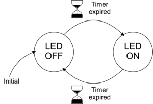
Blink state diagram
Code
The code below should be self-explanatory.
Some remarks on the code:
- The code uses #define preprocessor statements for defining settings.
- All variables have a global scope (i.e. they are known and accessible throughout the whole program).
- ledStep() is the function containing the code for the led state machine.
- Actions that need to be done when entering a state (usually initializations like resetting the timer variable) are done when leaving the previous state.
Download example code
