In this tutorial we will look at the usage of Infra Red light for sensing applications. Detecting the proximity of a person or object is simple using an Infra Red (IR) transmitter and receiver.
You can use them as “optical gate” (detecting the interruption of the beam) or in reflective mode (detection reflection of the beam) which can be a good alternative to the popular Sharp distance sensors.
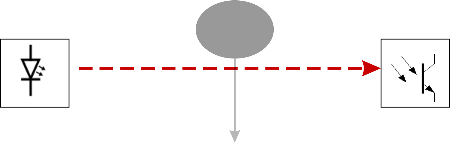 Optical gate configuration |
 Reflective sensing configuration |
Basic circuit
As IR transmitter we will use an IR LED controlled by a digital pin of a microcontroller e.g. Arduino. As IR receiver we will use a corresponding photo transistor.
Note: take care that transmitter and receiver work with the same wavelengths of IR as the IR spectrum contains a wide range of wave lengths. Check the datasheets for that.

Basic circuit for Infra Red sensing
This basic circuit will give you a reliable Infra Red light gate for short ranges. We will use short pulses of IR light, no continuous IR beam. That means you can use multiple transmitters and receivers on a single micro controller, or use one receiver and multiple transmitters from different directions. Because you can separate the pulses in time, they will not interfere with each other!
When used as an optical gate you can expect a range of a couple of meters, depending on how well you have optimised your optical path (good alignment is key here). In reflective mode you will only reach a few centimeters depending on the reflecting material.
Arduino code
The example Arduino code can be found below. The IR LED is connected to digital pin 7, the sense pin is analog input A0. The code measures the signal level difference without and while the IR LED is lit. The same code can be used combined with the pulse booster and signal amplifier circuits below.
Arduino program:
/*---------------------------------------------------------------------
IRranger.pde
Simple InfraRed proximity sensor
Herman Aartsen, februari 2013
-----------------------------------------------------------------------*/
int IR_LED_PIN = 7;
int IR_SENSE_PIN = A0;

void setup()
{
  pinMode(IR_LED_PIN, OUTPUT);
  Serial.begin(9600);
}

/* --------------------------------------------
Pulse()
Pulses the LED and returns signal level
-----------------------------------------------*/
int Pulse()
{
  int iHpulse;
  int iLpulse;

  iLpulse = analogRead(IR_SENSE_PIN); // measure low signal (= reference)
  digitalWrite(IR_LED_PIN, HIGH);  // switch on the LED
  delayMicroseconds(60);    // short delay to let signal settle
  iHpulse = analogRead(IR_SENSE_PIN); // measure high signal
  digitalWrite(IR_LED_PIN, LOW);  // switch off the LED

  return(iHpulse - iLpulse);
}

void loop()
{
  int iValue;

  delay(200); // wait for some milliseconds
  iValue = Pulse();
  Serial.println(iValue);
}
Increase the detection range
To increase the range you can do two things: use a stronger transmitter (increase IR light intensity) or amplify the received sensor signal. Increasing the transmitted light intensity is preferred as first step because amplification of the sensor signal might also amplify any disturbances resulting in a less stable sensing system.
Of course you can combine both increased intensity and amplification if you need even more range. Using the pulse booster and amplifier you can extend the range to > 25 meters in the optical gate configuration. When used as a proximity detector you will have a range of a couple of meters depending on the reflective surface. To measure distance it is best to use a diffuse surface such as paper.
Pulse Booster
To increase the range you can use a pulse ‘booster’. It will increase the IR intensity, which will increase your range by about 4x.
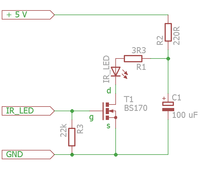 The pulse booster circuit |
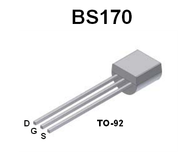 BS170 pin layout |
Working principle: use a short duration, high current pulse through the LED by discharging a capacitor through the LED. The capacitor will be charged (relatively slow) through R2. When the gate (G) of the transistor is raised to +5V (by the micro controller) the transistor starts conducting and the capacitor is discharged very quickly through the LED at a high current of about 0.5 A. This will result in a very intense IR pulse.
There is no risk of damage because the capacitor will be discharging fast and then the current will drop to a safe level. You may also put 2 LEDs in series, in which case you should use a smaller 2.2 Ohm resistor for R1. This circuit uses very little energy so you can power several transmitters from a single Arduino.
The circuit is based on a BS170 FET. The BS170 FET might not work with a Gate Source voltage (the input labelled IR_LED) of 3.3 Volt. The FET from the E-Lucid Starter Kit however, like the STU85N3LH5, will already work with a Gate Source voltage of 3.3 Volt.
Signal amplifier
The second way of improving range is to amplify the signal from the sensor. A circuit to achieve that can be found below. This amplifier which will again increase your range by about 3x. We will use an opamp as amplifier.
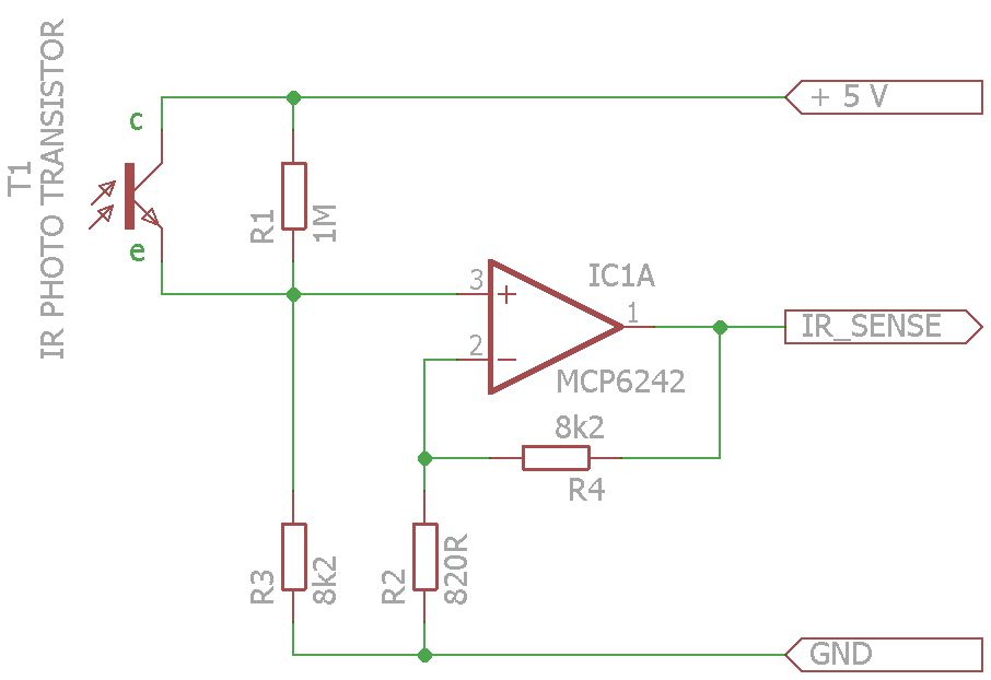 Signal amplifier circuit |
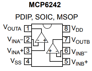 MCP6242 pin layout |
The opamp circuit is used in a non-inverting amplifier configuration, in this case amplifying the voltage on the +In input about 11 times. This voltage depends on the intensity of IR light received by the photo transistor. If the photo transistor does not conduct at all, the voltage will be very low (it is based on the voltage divider formed by R1 and R3). Once the photo transistor starts conducting, the voltage at the +In will increase and so will the output voltage.
Notes:
- Don’t forget to connect the power supply connections for the opamp to their respective pins (connect +5 V to VDD, and GND to VSS). They are not visible in the schematic as is common practice.
- The MCP6242 contains two opamps in a single casing. The pin indications in the schematic are for the first one (A, using pins 1,2,3) but you can of course use the other opamp as well. The circuit will also work with other OpAmps that work on a single supply voltage e.g. LM358
Tips
- Keep booster and amplifier circuit close to respective IR LED and the photo transistor to avoid electrical interference. So short wires from LED to driver stage and similarly from sensor to amplifier stage.
- Connect all GND connections to your micro controller GND.
- IR light can be very effectively blocked using materials that contain carbon such as Velostat and carbon foam.
- Use a retro-reflector (found in all bicycles stores) to reflect the beam back in reflective mode.
Acknowledgement
This tutorial is based on an earlier version developed by Herman Aartsen.