PWM what is it?
PWM is the abbreviation of Pulse-Width Modulation. PWM is a method of reducing the average power delivered by an electrical signal. This is done by switching it on or off in discrete time intervals at a fast rate. The longer the signal is on compared to the off periods, the higher the total power supplied to the load. The term duty cycle describes the proportion of on time in relation to the total cycle duration.
PWM what is it used for?
PWM is commonly used for applications where the switching on and off does not affect the expected function, think of speed control of DC motors (Battery operated power tools, fans in computers), control of the power of heating pads, and such. Another very common application is for the dimming of regular LEDs (human perception averages the fast blinking output). Servos are also controlled using specific PWM signals. Some sensors use PWM signals for communication of their measurements. Finally with some additional hardware for filtering, PWM can be used to emulate a continuous analog output, meaning to generate arbitrary voltages within a certain range from a on-off signal.
PWM why is it important?
Many microcontrollers do not have a means to regulate power output on their output pins. The outputs can only be switched on or off so the output will be the supply voltage (Vsupply, usually 5V or 3.3V) or 0V. It cannot be a value in between. It is all or nothing. This means that in order to regulate output power through microcontrollers you either need specific additional hardware or you need to do something smart: use PWM.
Most microcontrollers have PWM hardware and embedded software support built-in (for their PWM output pins). Of course, it is also possible to program a PWM signal in software for any digital output. Some microcontrollers have next to digital I/O pins one or more analog output pins that can generate arbitrary output voltages between 0V and their supply voltage (often 3.3V) through a built-in Digital-Analog Converter (DAC).
Another important aspect of using PWM is that switching on-off is power efficient. The switching component is either fully conducting (low voltage difference across) or not conducting at all (low/no current through). In both cases, the power consumption in the switching component is minimal, whereas the power consumption in in-between states is usually higher.
PWM in detail.
As mentioned before a PWM signal is a periodic signal usually expressed as repetition frequency fPWM (Hz). Associated with this is the period TPWM (s): $T_{PWM} = \frac{1}{f_{PWM}}$
The duty cycle d is defined as the fraction of a period the signal is high and usually expressed in percent.
Below animation shows a PWM signal having a constant frequency or period but a varying duty cycle.
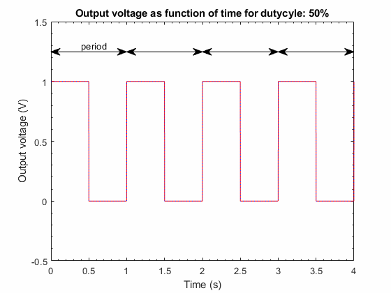
The voltage as function of time for a PWM signal in a single period TPWM can be described as: the signal is equal to Vsupply for time t between t = 0 and t = d.TPWM and it is equal to 0V for the remainder of the period from t = d.TPWM to t = TPWM.
In a more mathematical form:
$$
V\left(t\right)=
\begin{cases}
V_{supply} & \text{for } 0 \leq t \lt d.T_{PWM}\\
0V & \text{for } d.T_{PWM} \leq t \lt T_{PWM}\\
\end{cases}
$$
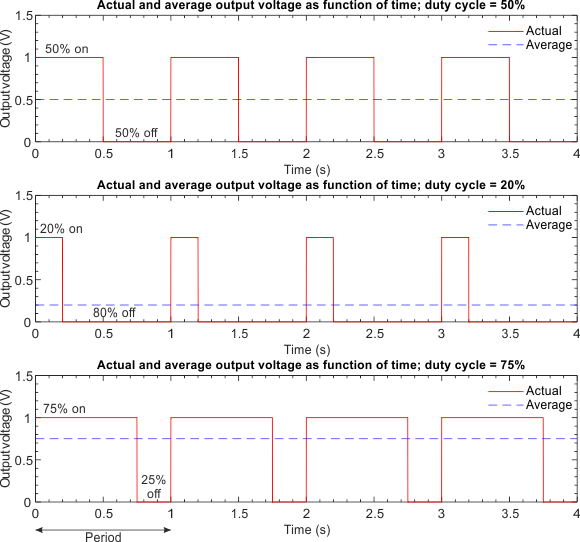
The average output voltage Vavg of a PWM signal having a period TPWM, maximum voltage Vsupply, and duty cycle d, can be calculated as:
$$
\begin{align}
V_{AVG} &= \frac{1}{T_{PWM}}\int_0^{T_{PWM}}V(t)dt = \frac{1}{T_{PWM}}\left( \int_0^{d.T_{PWM}}V_{supply}.dt + \int_{d.T_{PWM}}^{T_{PWM}}0.dt \right)\\
&=\frac{1}{T_{PWM}}\left[ d.T_{PWM}.V_{supply} + 0.T_{PWM}.\left(1-d\right) \right] = d.V_{supply}\\
\end{align}
$$
In words the average output voltage is the duty cycle times the supply voltage. Some examples can be seen in the below figure.
Relation (average) power and dutycycle
In a resistive load the power dissipated is given by: $P = V.I =\frac{V_{supply}^2} {R}$
A calculation similar to the one before will show that in case of a PWM signal having dutycycle d the average power PAVG is given by:
$$P_{AVG} = d.\frac{V_{supply}^2} {R}$$ In words: the average power is proportional to the dutycyle. This makes controlling average power relatively easy using PWM.
For non-resistive load the phase difference between current and voltage needs to be considered in the calculation of course.
The above text-only covers the basics. More background information can be found on the Wikipedia page on Pulse-width modulation.
PWM and microcontrollers?
Most microcontrollers have built-in PWM functionality on a number of I/O pins. The PWM frequency is derived from the clock frequency of the microcontroller and is usually in the 500 – 1000 Hz to a few kHz range. In Arduino code, it can be applied for the PWM pins through the analogWrite() function.