The IS471F is an optical light sensor, mainly used as object detector. The sensor is combined with an external IR (infra red) LED. When the IR light emitted by the LED is reflected into the sensor by an object, its presence is detected. The range however is limited to approximately 15 cm.
LED’s can endure a higher current over a short period and emit more light. With this increase in brightness you will be able to extend the range to 50 cm or more.
The circuit
The circuit combines the Sharp IS471F with a PNP Darlington transistor and potmeter to boost and adjust the LED current.
The LED current can be adjusted from 0 to 1A (pulsed peak current; so a high current but for a very short duration) by varying the base current of the transistor with the potentiometer.
Note: Of course this circuit consumes extra power.
The IR LED has to have a narrow opening angle to bundle all the light on the sensor and should be able to handle peak forward currents up to 1A. We have chosen a 10° LED (measured half angle). A wider opening angle will work, but than the maximum distance is less. Advantage will be that the alignment is less critical.
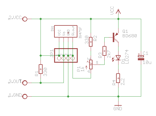
The supply voltage is 5V. When you only want to use the sensor with its maximum range, you can leave out the potmeter and connect GLOUT to R3 and R2 directly. The circuit will also work with other supply voltages, but the values of the currents are calculated for a supply voltage of 5Volt
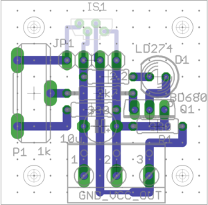
Below a suggestion for Printed Circuit Board layout with a small footprint is shown. The sensor, IS1, is shown only to indicate the correct orientation. The sensor should actually be placed at the position of header JP1 with or without the use of headers. The dots are just to indicate the holes of the prototyping board. Making it easier to copy the circuit.
In the end you should end up with something similar to the image below.
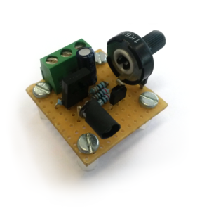
Note: to prevent direct reflections of the IR LED into the sensor we covered it with a heat-shrink sleeve.