A digital multimeter (short DMM) is a tool that assists in the process to explore what’s happening inside components or in a circuit. Or when debugging your circuit.
This guide will shortly explain how to setup your Digital Multi Meter and how to use it to do different measurements.
Important for correct understanding:
Ohm’s principal discovery was that the amount of electric current through a conductor in a circuit is directly proportional to the voltage impressed across it. Similarly we speak about a current through or a voltage across a (part of) a circuit. Please don’t make your own ‘blend’ of this. Voltage never goes through, current is never across !! Using the correct phrasing will help you avoid making measurement mistakes.
Multimeter basics.
Every meter multimeter has a “common” socket, color-coded black and labeled “COM”. Plug the black probe into this socket.
You’ll also find a red-coded socket, labeled with the letter V and an ohm (Ω) symbol to indicate that it measures voltage (difference) and resistance. Sometimes it is also labeled mA, then you can measure small currents in milliAmperes (mA) up-to the indicated value using this socket.
But mostly there is again a separate socket for measuring currents. Sometimes, yet another socket is set aside for high currents, up to 10 amperes (A).
First consider what you want to measure. This could be current, voltage, resistance, capacitance, continuity, gain, frequency. And very useful when available: diode polarity and forward voltage (also for LEDs).
Connect your red probe to the appropriate socket and turn the selector dial to the quantity that you want to measure before you touch the probes anywhere. Some multimeters are auto-ranging, while others have to be adjusted manually to the desired range (e.g. you select the 20 Volt range or the 2 Volt range). Usually auto-ranging meters can also be set manually for example to avoid waiting times related to the auto-ranging functionality.
One more thing before we start: Sometimes the display shows O.L. This is short for overload. Meaning the measured quantity is larger than can be displayed in this setting.
Measure resistance.
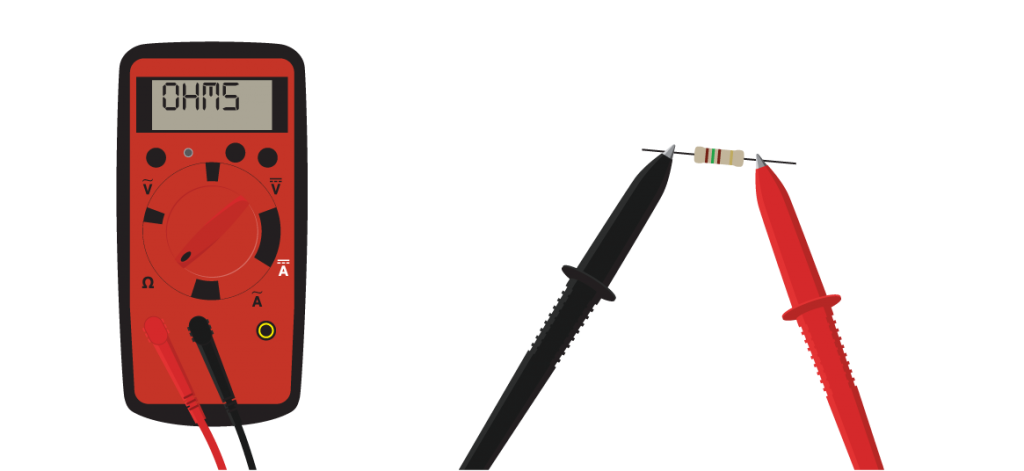
To measure the resistance of a component, disconnect the component from your circuit (because the multimeter will apply a voltage difference to the leads to be able to measure resistance). Connect the probes to the correct socket (black to Common, red to the socket labeled Ω). Switch the multimeter to the correct setting for measuring resistances and if needed correct resistance range (higher than the expected value). Connect a probe on each side and read the value from the display. The value in ohms (Ω) or kilo ohms (kΩ; 1 kΩ = 1000 Ω) tells you how difficult it is to pass an electric current through that component. Common resistor values can go up to several Mega ohms (MΩ; 1 MΩ = 1000 kΩ or 1000000Ω). Mind the capital M (the small m is reserved for ‘milli’).
Since your skin resistance can be in the order of magnitude of several MΩ, touching the probe tips might influence your measurement when measuring large resistor values.In that case your skin resistance is in parallel with the actual resistor.
If you see strange readings, check your meter: Double check if you have used the right input sockets, and if the probes are pressed in firmly. Default reading on the display is OL (Open Loop or Over Load, meaning infinite resistance in this setting). Connecting the tips of the probes (i.e. shorting both ends of the two probes) should result in a 0 Ω reading. If not, check again things as mentioned before. And check if using another probe gives a better result. Also, warnings on empty batteries should be taken serious.
Measure voltage difference.
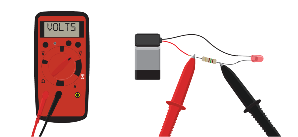
To measure voltage differences connect the probes to the correct socket (black to Common, red to the socket labeled V). Switch the multimeter to the correct setting for measuring voltages and if needed correct voltage range (i.e. higher than the expected voltage). Touch the black probe to the negative (“-“) side of the power supply, touch the red probe to any other location in a circuit, and you’ll monitor the voltage difference (the difference in electric potential energy per unit electric charge) between them. If you have an auto-ranging meter, it takes a moment to respond. A manual meter is faster, but you have to turn the dial to specify the upper limit of the voltage range. Voltage differences are indicated in volts (V) or millivolts (mV; 1 mV = 0.001 V), sometimes even in microvolt (1 μV = 0.000 001 V).
Checking voltage difference is the most basic way to troubleshoot a circuit — you can look for bad connections, burned-out components, or a dead battery. Systematic problem solving works best here. Have a schematic diagram at hand. Compare measured voltages with the ones you expect to measure, or the ones you have calculated.
Voltage differences are always measured across (parallel to) a component or (part of) your circuit!
Measure current.
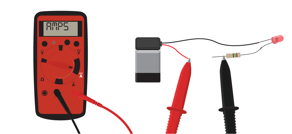
To measure current connect the probes to the correct socket (black to Common, red to the socket labeled mA or A depending on the expected value of your current). Switch the multimeter to the correct setting for measuring currents and if needed correct current range (i.e. higher than the expected current).
Current consists of a flow of electric charge (most of the times through electrons). Pass current through the multimeter cautiously. Multimeters have internal fuses for protection from too high currents. Too much current will blow the internal fuse which will disable current measurements (so when a multimeter always indicates no current, check the fuses).
In the Ampere setting, meters have a very low internal resistance to pass through and not influence the current. That is also why you mostly need to use different input terminals when measuring current. So when trying to measure current, never attach both probes of the meter directly to a power source, or anywhere in parallel to your circuit. You will at least blow a fuse and may destroy the power source and/or your circuit as well (When you do this with rechargeable batteries, they might catch fire!).
Currents can be indicated in amperes (A), milliamperes(mA; 1 mA = 0.001 A) or microamperes (μA; 1 μA = 0.000 001 A).
Currents are always measured through (in series with) a component or (part of) your circuit!
Diode checking.
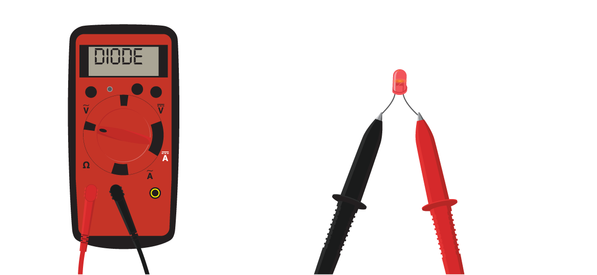
Some multimeters are equipped with a special “diode check” function, usually indicated by a diode “![]() ” symbol, which displays the actual forward voltage drop of the diode in Volts. These meters work by forcing a small current through the diode and measuring the voltage drop between the two test leads. In this way you can identify which of the leads of the diode is the the cathode (negative side)/anode (positive side), and whether the diode is broken shorted, or broken with an open circuit. If an LED is connected correctly it will light up. Some multimeters however apply a voltage at the terminals that is too low for operating a LED (or for a LED with a higher forward voltage for example white or blue LEDs). Check the manual of your multimeter for details.
” symbol, which displays the actual forward voltage drop of the diode in Volts. These meters work by forcing a small current through the diode and measuring the voltage drop between the two test leads. In this way you can identify which of the leads of the diode is the the cathode (negative side)/anode (positive side), and whether the diode is broken shorted, or broken with an open circuit. If an LED is connected correctly it will light up. Some multimeters however apply a voltage at the terminals that is too low for operating a LED (or for a LED with a higher forward voltage for example white or blue LEDs). Check the manual of your multimeter for details.
Measuring AC current and AC voltage differences.
Most simple electronic circuits use DC (Direct Current) power, but most multimeters can measure AC (Alternating Current) too. Many have an AC-DC button, but some have AC options on the selection dial indicated by addition of a “∼” symbol whereas DC options are usually indicated through a “![]() ” symbol. If multimeters have an AC setting they will measure the so-called RMS (Root Mean Square) value and this is usually configured to be correct around frequencies of 50 to 60 Hz. The value is not correct for higher frequencies.
” symbol. If multimeters have an AC setting they will measure the so-called RMS (Root Mean Square) value and this is usually configured to be correct around frequencies of 50 to 60 Hz. The value is not correct for higher frequencies.
To analyse analog and digital signals that change over time, an oscilloscope and not a multimeter, is the tool to go for.
Different types of multimeters.
In the tutorial above you see a so called handheld multimeter. They are very handy because you can carry them anywhere you need them. Another kind of multimeter is the benchtop multimeter, often found in lab spaces, like the E-lab. These multimeters are mains powered. But the general functionality is the same.
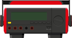
Some remarks about the UT803 multimeters as used in the E-lab.
- When it is not used for a certain amount of time it automatically switches off. Rotating the dial will wake up the instrument.
- For measuring temperatures a special temperature probe is available at the E-Atelier desk
- The read more section on this page links to a video tutorial for this multimeter. To help you watching, we have made this list: